
Continuous flight auger piles (CFA), also known as Augercast piles, are deep foundation elements that are cast-in-place, using a hollow stem auger with continuous flights. The first applications of CFA method were begun in 1950s in the USA.
The auger is drilled into the soil and/or rock to the design depth. The auger is then slowly extracted, removing the drilled soil/rocks. Concrete or grout is pumped through the hollow stem. This common practice has been improved by BST manufactured pressure and concrete pumping system to extend the footage at desired depth to increase load capacity.
Piles are drilled to its final depth in one continuous process using a continuous flight auger. (Figure 1-a) While the auger is drilled into the ground, the concrete feeding tube kept capped during the drilling since the flights of the auger are filled with soil, mud and/or water which provides lateral support and maintains the stability of the hole.
The most common auger diameters in the USA are 300, 350, and 400mm. The Japanese contractors built augers as wide as 1 meter in diameter. The preferred auger diameters used in Europe are increasing as well. The pile length can be up to 41 meters with diameter of 1.5 meters. However, the most common depth for piles are between 6 to 20 meters.

As the augers are withdrawn from the hole, concrete or grout is placed by pumping the concrete/grout mix through the hollow center of the auger pipe to the base. The concrete pumped in can be 500 dose (0-8 aggregate), 450 dose (0-16 aggregate), or 400 dose (0-25 aggregate). The grout/concrete mix pumped in blows off the expandable cap and places soil as the auger is removed.
(Figure 1-b) The pressure injected concrete interpenetrates into the soil which provides good adhesion between the pile and the soil as well as compresses the soil. The auguring in hard clay soil leave helical grooves. (Figure 3) Augers can be pull out by rotating or not while concrete is pumped in. The pull out speed (rate) is related to the concrete pump speed. This construction method can be used in various soil conditions. The sound and vibration levels are low during the process.

Reinforcementbars (rebars) are placed into the fluid grout/concrete immediately after the auger is removed. The reinforcementbars can be consistent of full length. (extends the entire depth of the pile) Single rebar placed in the center of the hole or preformed rebar cage built according to pile diameter, (Figure 1-c) (Figure 4) except for end piles. This method makes it possible to use the reinforcementbars at the desired length for moment constraint of the pile.
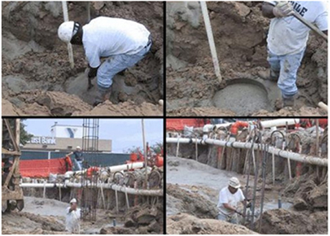

In case of difficulties to settling the rebar cage the piling machine’s vibratory drive head can be used to set the cage in place. (Figure 5)
The application time varies depending on the pile length and the soil type.
The calculated pile length can be controlled during the pile construction by constantly measuring the pressure and torque applied during the insertion of the auger to the soil and by continuously monitoring the soil sample coming out to the surface of the pile during the retraction of the auger. Project calculations and pile length can be revised if significant changes are required by the inspection results.
Constructed piles are load tested according to the TSE (Turkish Standards Institute) and EuroCode7 norms. This method was introduced to the German norms (DIN 4014 G2C5) in 1991 and is the most widely used pile construction method in developed countries.
Specification details;
http://www.fhwa.dot.gov/engineering/geotech/pubs/gec8/gec8.pdf
http://www.fhwa.dot.gov/engineering/geotech/pubs/gec8/

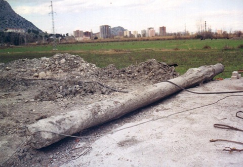
Here is a BST Produced naked CFA
DRILL SHAFT SOCKETED INTO ROCK

Auger pile drilling attached with special drill or hammer apparatus to the pile can be inserted to the rock at desired length. The pressure strength and torque moments can be monitored with hydraulic gauges as well as the type of the soil continuously monitored by drill samples surfaced by auger removal process.
The bearing load capacity of the pile increased by expanding the footage above the rock level during pumping concrete and pulling auger out.
BST METHOD OF GROOVED PILE APPLICATION

Auger flight drills to the calculated depth. Then the concrete is pumped into the hollow shaft to blow of the cap and pushed to the bottom. Concrete pumping with pressure continues as the auger is pulled out without rotation.
After pumping sufficient concrete into sheath the auger is driven in with machine’s pressure into the hole. The procedure continues with the withdrawal and pushing the auger into the pile hole while concrete is pumped in until required pile diameters at required depths are provided by compacting the soil. This procedure creates a grooved pile form with required depth, diameter and number.
The method and the equipment was developed by BST Engineering. This method of pile construction does not require any special technique or equipment attachment. The procedure is done by simple lever motion by the operator of the machinery.
The load capacity of the pile and the soil strength can be estimated during the piling process by monitoring auger plow and pressure which procures the construction control and revise calculations if necessary.
BST Grooved Pile manufacturing is rapid and cost-effective to provide optimal solutions. The tests show that load bearing capacity and the tip shear capacity of the smaller diameter BST Grooved piles are near large diameter regular piles.
Consequently, the BST Grooved Pile Method provides the high bearing capacity allowed by the soil economically.


